
This entry is going up a little later than I would have liked to to go up, but I guess late is better than never, right? This past spring break I made some projects for myself to try to hone some skills that I plan on utilizing for my career later in life. Not only that, but some of them were fairly practical. One such project was modifying my American NES to play audio from enhanced Japanese Famicom carts. I had a previous post explaining the whole thing. Here’s a Cliffs Notes of the whole thing. In Japan, on the Famicom (NES, but Japanese), there was an extra pin that allowed developers to make their own enhancement chips to mix into the audio. This was not put into the NES when it came to America because there were much stricter policies for publishing games and it only allowed for the use of a handful of chips to be used.
Step one for the whole thing to work is to acquire a Famicom to NES converter, and a game that used a sound enhancement chip. Luckily, I had both of these already so now I just had to figured out how the whole thing worked. To my unsurprised I found that this modification was already done many times and pretty detailed information was already given on it.
The process included taking the audio out pin from the adapter and passing it through a 100k ohm resistor and a 4.7 μF capacitor then to the R9 resistor on the NES main board. The resistor and capacitor help with the volume in the mixing because without them the extra audio channels added in would be too loud and we wouldn’t hear any of the default audio channels.
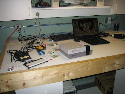
Let’s get this party started.
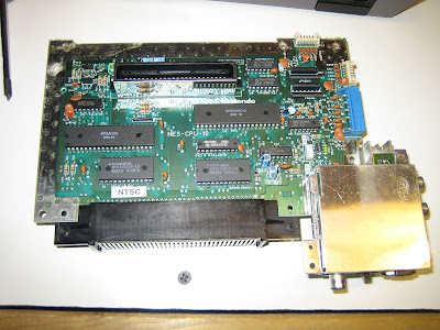
Top of the NES board
Wire soldered to R9 (labeled on the top of the board)
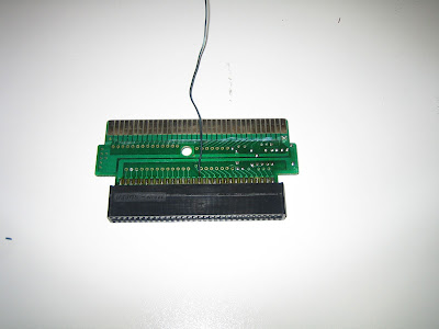
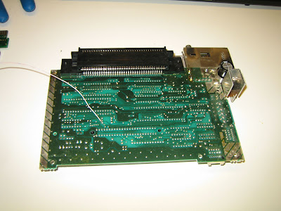
Wire Soldered to pin 16 of the adapter cart
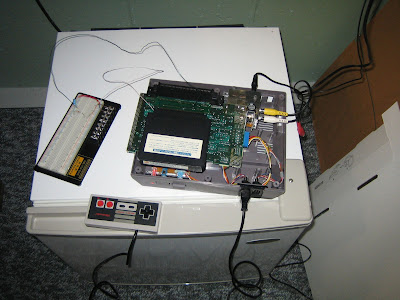
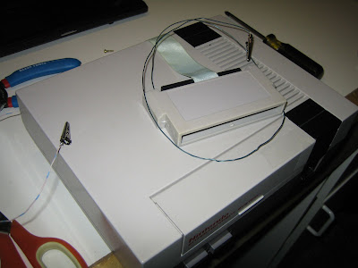
I wanted to make sure it worked before I soldered it on a board
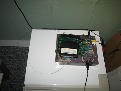
You can see the finished board by the power button
While I was in there I was wondering if there were any other mods I could do. I found out by just knocking out pin 4 of the infamous “lock-out chip” I could disable it. Technically you are supposed to connect pin 4 to ground, but almost everything I read said that leaving it floating is fine. This chip was supposed to keep any old company from making games without going through Nintendo (greedy bastards!). Of course many companies found a workaround for the chip, most famously Tengen. Tengen actually finagled the information from the US Copyright Office and reverse engineered a solution. They were sued outright. Why would I care about disabling the lock-out chip? Well, if you are an NES gamer and remember back to when the thing used to reset constantly and you would have to take the cart out and blow on it and stick it back in. That is the lock-out chips doing. If the pin that loaded the data to tell the lockout chip, “Hey, I’m legit, let me play.” didn’t connect the game wouldn’t load. If you were a kid who grew up on this, you absolutely know what I am talking about.
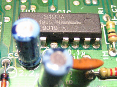
Here is the death of the lock-out chip.
The finished product.
Here is a video of the proof. VRCVII audio coming out of the NES. Success!
I want to modify it to use a 3.5mm plug and input, but I will save that for another time.
I have a couple more projects I have been working on and will post them shortly.
*Update*
I made some changes to the mod and made a video.